Hi all,
after planing and debating, weighing Pros and Cons, drawing Plans and Sketches I finally got my Unit installed and was more than happy that everything worked out as planed.
My Boat is 1971 VICTORIA 27, proudly built in GERMANY by a Shipyard that went bankrupt in the late 70s

. She's got a Fiberglass Hull and has two VOLVO PENTA AQ 115 Inboard Engines with AQ 100 Z-Drives.
The first Problem I ran into after getting my 981 from G-COMM in the UK was the sheer Size of the Transducer. I didn't expect a Surf Board has to find a Place at the Rear End of my Boat

!
Anyways, in Order to get clean Shot to both Sides of the Transducer I had to find a Solution to get underneath Keel Level. I was afraid that the Keel would block the Sight to the right, if I would mount the Ducer in the same Place where the Ducer of my old Fishfinder was mounted.
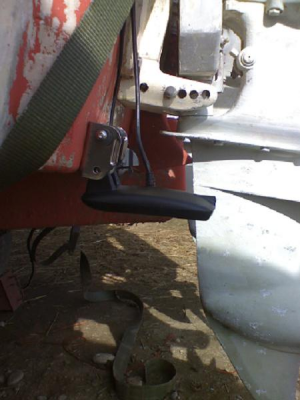
So I was thinking about getting it underneath the Boat and to cut out a Piece of the Keel, where I would mount it on a Jack Plate:
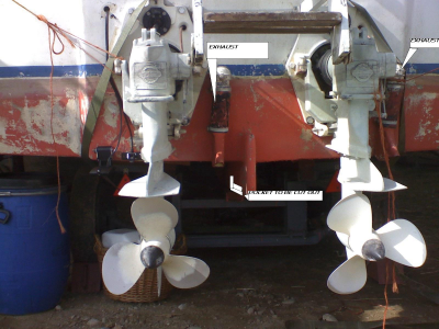
What looked good on a first Look, wasn't good after thinking about it: The Ducer would be the lowest Part of the Boat and there would be no Chance for it to get out of Harm's way if the Boat would hit the Ground for any Reason. On Top of that, every Time that I want to adjust it, I would have to dive down to it. Getting the Dive Gear on just to adjust the Tilt Angle for five Degrees was not what I wanted to do.
So Plan "B" was due to be executed. In Order to get below Keel Level and to have an easy Possibility for the "Fine Tuning" of the Adjustments, I decided to build a "Telescope Mount". This Way, it would be possible to get good Side Scans and High Speed Readings without being worried of wrecking the Ducer in shallow Waters.
Now here's what I did:
I got two Stainless Steel Pipes which fit into each other. One would function as the "standing" Part, holding the second "moving" Part in Place. By using round Pipes instead of square Pipes, one has the Opportunity to line up the Ducer in Drive Direction easily.
Once lined up, the Transducer has to be kept in the Drive Direction to stay rectangular to it. Therefore I cut a "Guiding Line" into the outer Pipe. The Length of this Guiding Line was the Length of the Way I wanted the Ducer to be lowered or raised (20 cm).
To avoid that the inner Pipe moves out of Driving Line, I cut a Thread for a 5mm Screw into it and secured the Screw with LOCTITE. This Way the inner Tube wouldn't fall out of the outer Pipe and the Screw would hold the Ducer/inner Pipe lined up rectangular to the Driving Direction. Since I wanted to have a back up Safety for the single 5 mm Screw, I cut two extra Threads on the Top End of the inner Pipe for two additional Safety Screws (I admit that my German overengineering Tendency broke through here

).
Another Issue that had to be solved was to get the Ducer lined up horizontal to the Surface and a bit tilted down with its Rear End. Therefore I decided to built a Jack Plate. This done, a Friend of mine welded it to the inner Pipe and I could bolt the HB Bracket to it. Using the HB Bracket keeps the Opportunity that the Ducer can "kick up" if it hits something.
Now, after a long Powhow here are some Pictures. I hope they are more "explainative" than my not so good Technical English Expression Capabilities.
Installation Details
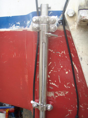
Side View lowered
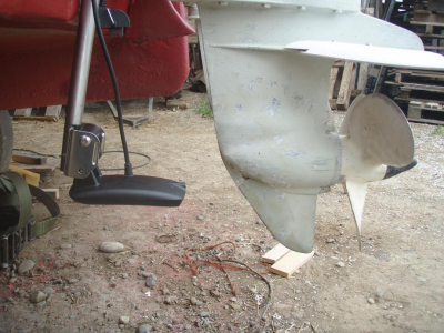
Side View raised
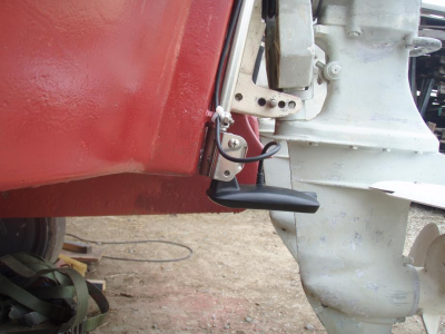
Rear View raised
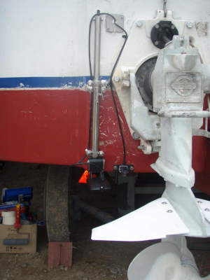
Rear View lowered.
Note that the Ducer is too low/close to the Prop and will cause Cavitation to it. That didn't happen by Accident but has a Purpose: It has the Side Effect, that I don't forget to raise the Ducer up if I want to speed off with the Ducer lowered. The Ripping Force at high Speed might be too big for the Installation. The inner Pipe might get bent or the hole Installation might get ripped off from the Transom.
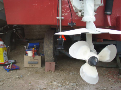
To get the whole Gig mounted to the Transom, I drilled six Holes THROUGH the Transom Plate and used 8mm Stainless Steel Screws instead of regular Wood Screws, which would be screwed just IN the transom plate.
The Idea behind it is that one still can get the whole Thing off or loosen the Nuts for Adjustment while the boat is in the water AND one doesn't have to worry about getting Water into the Fiberglass.
Well, that's about it. Everthing worked as planed when I finally got my Boat in the Water two Weeks ago. Just had to adjust the Tilt Angle of the Ducer a Bit to get nice 2D Bottom Readings at high Speed.
I want to thank Robert and John for their Input, Thoughts and Ideas at this Place and I hope someone will find some Help in this if he's about to become "a fully armed Bass seeking Missile"

.
Regards from Lake Constance
Harry